上 angularity tolerance zone 242655-Perpendicularity tolerance zone
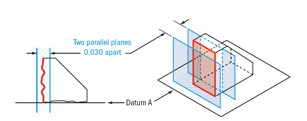
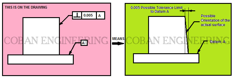
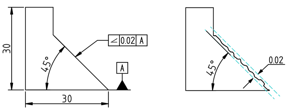
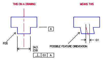
An angularity specification controls how much the feature can deviate from a specified angle to a datum Sometimes you can use a secondary datum to control the tolerance zone's orientation For this geometric tolerance, these three aspects work together Each considered feature and each resulting toleranced featureAnswer to When an angularity tolerance is applied to a planar surface, the tolerance zone is two parallel planesSo geometric tolerance is defined which limits the amount a surface, axis, or center plane is permitted to vary from being perpendicular to a datum which is known as perpendicularity control It creates a tolerance zone that consists of two parallel planes separated by the geometric tolerance
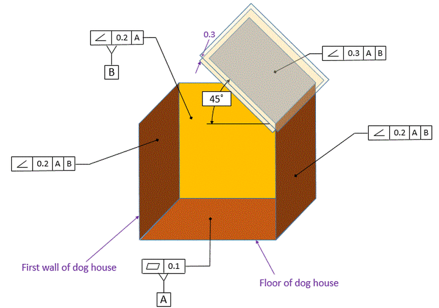
Angularity Dimensional Consulting
Perpendicularity tolerance zone
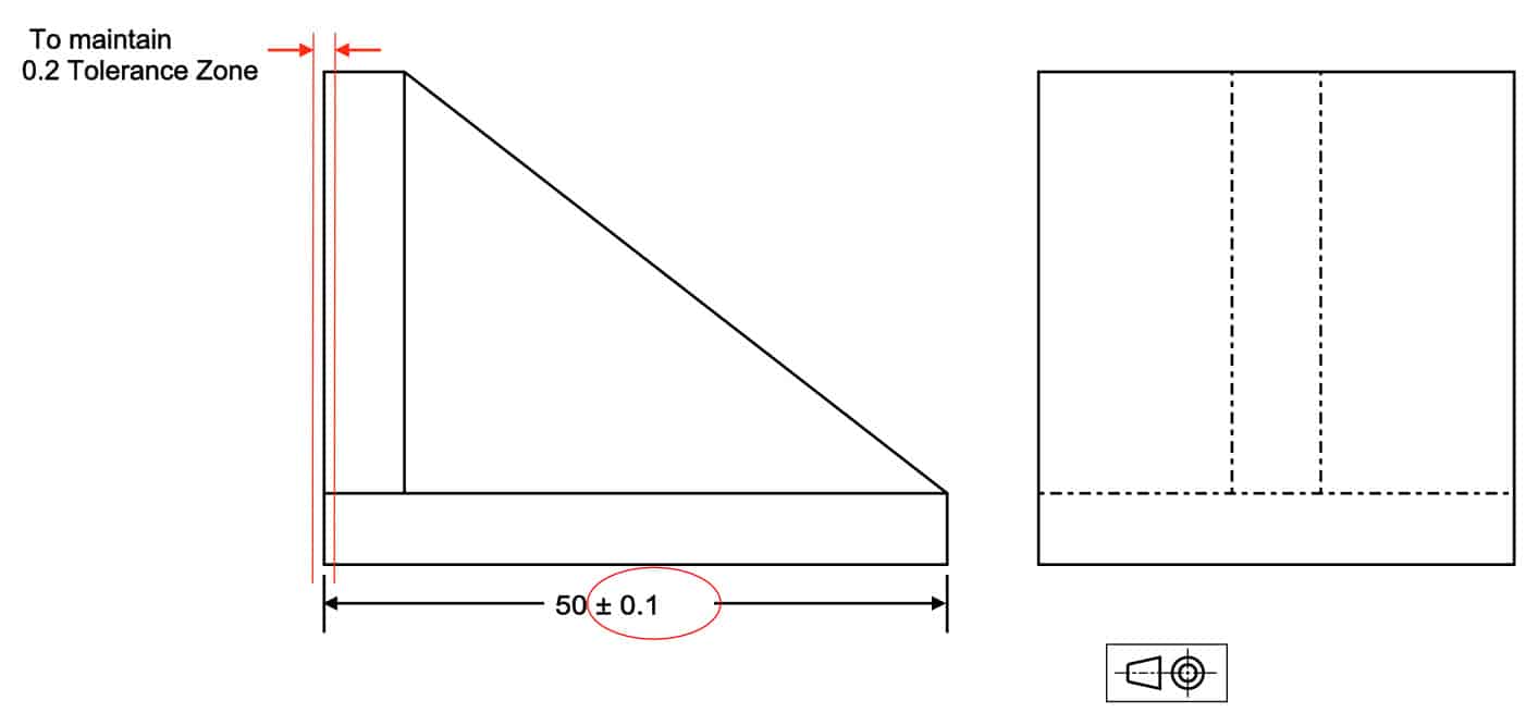
Perpendicularity tolerance zone-The shape of the tolerance zone for parallelism is 2 parallel planes with thickness as mentioned in tolerance value In below example, all the elements of the surface must lie within this tolerance zoneSpecial Note Perpendicularity in GD&T can mean two very different things depending on which reference feature is called out The normal form or Surface Perpendicularity is a tolerance that controls Perpendicularity between two 90° surfaces, or featuresSurface Perpendicularity is controlled with two parallel planes acting as its tolerance zone
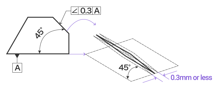


Orientation Tolerance Types Of Geometric Tolerances Gd T Fundamentals Keyence America
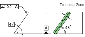
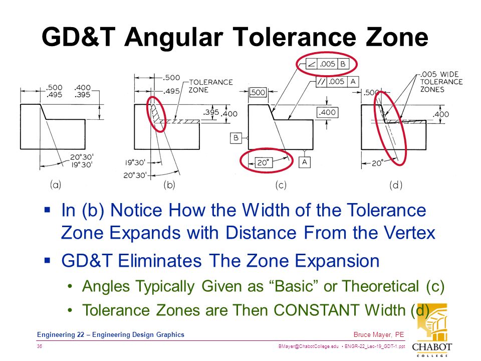
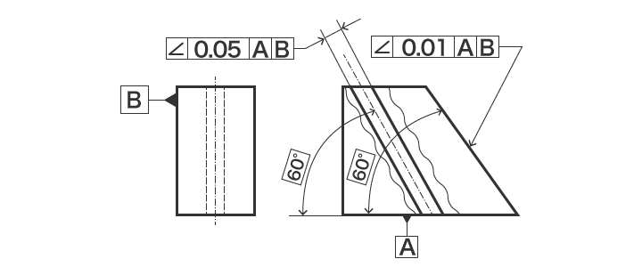
The tolerance zone for the angularity zone is a linear dimension and not an angle So whatever your value is, it's given in inches or mm I'm guessing by your post that it's 2 mm Also, the tolerance value given in the feature control is a total value and not a / valueSo Angularity symbol may be interchangeably used in place of Parallelism and Perpendicularity What is Parallelism in Drawing?Angularity Tolerance Zone Angularity tolerance zone can be specified by one of the following · A tolerance zone defined by two parallel planes at the specified basic angle from one or more datum, planes, or axis, within which the surface of the specified feature must lie
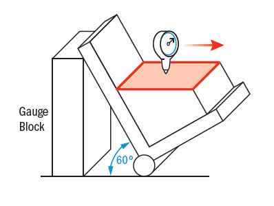
Angularity describes the specific orientation of one feature to another at a referenced angle Automated Gage Systems Automotive Concentricity is a complex tolerance used to establish a tolerance zone for the median points of a cylindrical or spherical part feature Concentricity is generally reserved for highprecision parts, and onlyThe tolerance on this part for B is 010 perp to A So, I am wondering, if B is perp at the limit to A (010 perp), and the hole is at the limit at 010 perp to A, is it possible for the hole to be out to B?Roundness tolerance zone is two concentric circles Roundness is a radial measurement, not diametral Precision Spindle Circularity (Roundness) A precision spindle (or CMM) could be used Angularity Requirement Tolerance Zone Angularity measurement is also a TIR
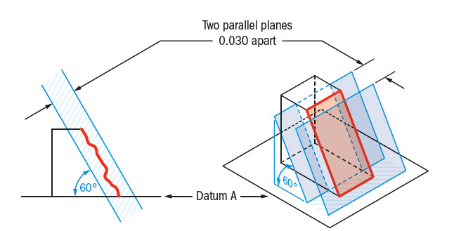
Also Angularity tolerance zone can be defined as a threedimensional geometric tolerance that controls how much a surface, axis, or plane can deviate from the angle described in the design specifications LMC or MMC can apply to feature of sizeTolerance zone is a specified space separating two parallel planes Angularity • An angularity tolerance is used to control angular relationships of any angle between straight line (axes) or surfaces with straight line elements such as flat or cylindrical surfacesDescription Angularity is the symbol that describes the specific orientation of one feature to another at a referenced angle It can reference a 2D line referenced to another 2D element, but more commonly it relates the orientation of one surface plane relative to another datum plane in a 3Dimensional tolerance zone The tolerance does not directly control the angle variation and should not
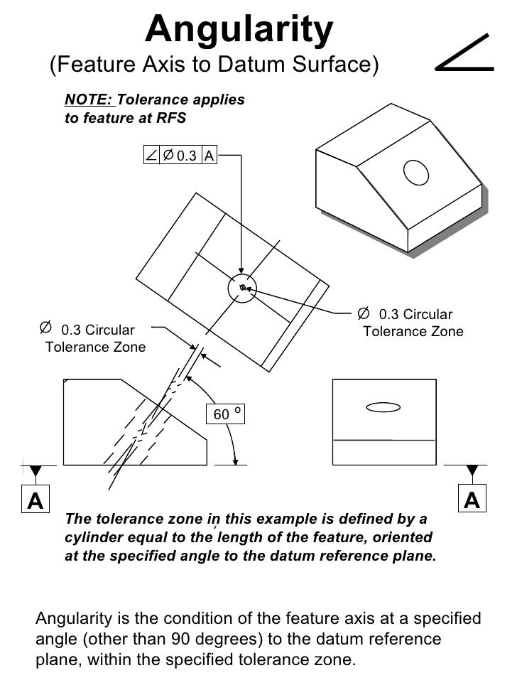


Gd T Presentation1111


Faculty Uml Edu Bkim 22 1 Tolerance1 Pdf
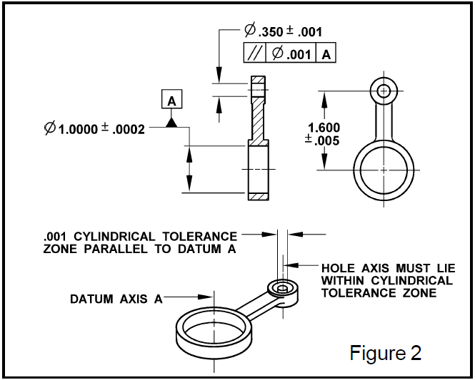
This page explains the 16 symbols used in GD&T, and the classification thereof The true position theory and the specification of tolerance zones are also explained "Learning GD&T From Scratch," provided by KEYENCE, walks you through the basics of geometric dimensioning and tolerancing, datums, and measurements by coordinate measuring machinesIn a mechanical drawing of a part, angularity tolerance allows the designer to specify the degree to which the orientation of an angled part feature may vary The angularity symbol is often used to insure that the part can properly mate with another In GD&T, the degree of permissible variation is not specified as a tolerance on the angleProjected tolerance zone symbol In the case of a tolerance of orientation (angularity) and position, the tolerance can also apply to the external projection of it and NOT to the tolerance itself, hence this is a projected tolerance zone Learn more about Chapter 11 Projected Tolerance Zone on GlobalSpec


Gd T Angularity Introduction Youtube


Http Web Aeromech Usyd Edu Au Engg1960 Documents Week13 Engineering drawings lecture linear geometric tolerancing 14 Pdf
Answer to When an angularity tolerance is applied to a planar surface, the tolerance zone is two parallel planesAngularity describes the specific orientation of one feature to another at a referenced angle Automated Gage Systems Automotive Concentricity is a complex tolerance used to establish a tolerance zone for the median points of a cylindrical or spherical part feature Concentricity is generally reserved for highprecision parts, and onlyThe shape of the tolerance zone for parallelism is 2 parallel planes with thickness as mentioned in tolerance value In below example, all the elements of the surface must lie within this tolerance zone
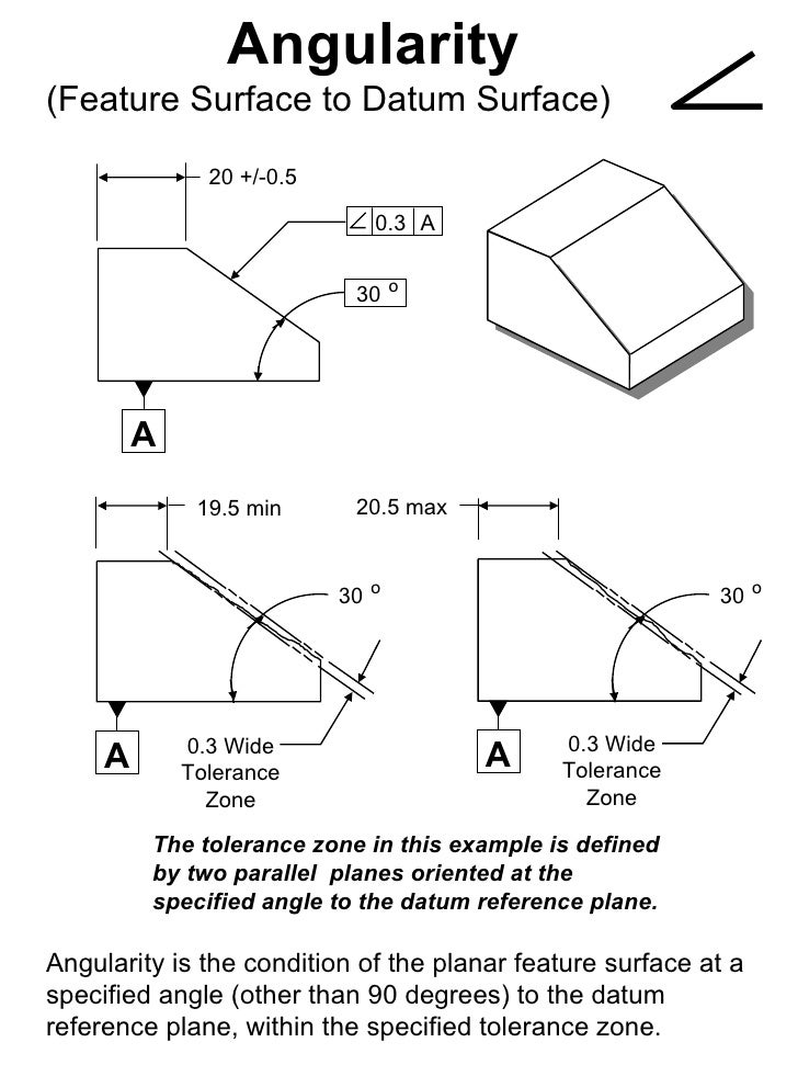


Gd T Presentation1111


Geometric Tolerancing Engineering Drawing Joshua Nava Arts
Angularity Tolerance Feature Control Frame Angularity to a Surface Angularity to a Center Plane Angularity to an Axis 110 Angular Tolerances Traditional methods for tolerancing angles require that angled surfaces be very accurate near the vertex of the angle, but can vary more along the length of the angled featureQuestion Specifies A Tolerance Zone At Right Angles To A Given Datum Or Axis A Perpendicularity B Angularity C Parallelism D Profile 8 An Orientation Geometric Tolerance Controls The Degree Or A Parallelism B Perpendicularity C Angularity D All Of The Above Represents A Surface In Which All Points Are An Equal Distance From A Common Center A Position1 The tolerance zone is two parallel planes oriented by the basic angle to the datum features referenced 2 All elements of the toleranced surface must lie within the tolerance zone 3 The flatness of the surface is also controlled within the angularity tolerance zone


What Is Angularity Tolerance And How To Interpret In The Drawing Mechstandard


Hsm Machining Reference Gd Amp T Reference
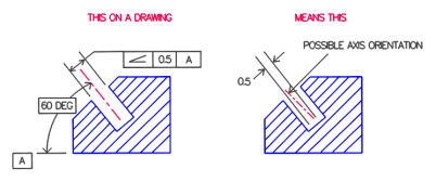
Angularity Pro˜le of a line True Position Concentricity Symmetry Runout Total Runout Pro˜le of a surface True Position (Maximum Material Condition) Flatness (Derived Median Plane w/ )M M M M M SYMBOL NAME ON DRAWING TOLERANCE ZONE GAUGING GD&T Symbols and Guidelines Cheat SheetProjected tolerance zone symbol In the case of a tolerance of orientation (angularity) and position, the tolerance can also apply to the external projection of it and NOT to the tolerance itself, hence this is a projected tolerance zone Learn more about Chapter 11 Projected Tolerance Zone on GlobalSpecGD&T Angularity Tolerance Zone when applied to a Surface Angularity tolerance in GD&T is used to control how one feature or surface is oriented at an angle with respect to the datum plane It does not control the angle of a surface, Angularity controls how much a surface can vary from a true surface at the basic angle from the datum plane or


Examples Gdt Datum Axis Page 1 Line 17qq Com


Perpendicularity Gd T Basics
Datum references (if required by the GD&T Symbol) Combined, the feature control frame provides all the information you need to measure the geometric tolerance of the features of the part and determine if the part is in specAngularity The tolerance zone is limited by a cylinder of diameter t if the tolerance value is preceded by the symbolThe projected tolerance zone specifies the vertical tolerance zone (protrusion) of an embedded part, such as a pin or bolt This page explains the symbols used and provides sample drawing indications "Learning GD&T From Scratch," provided by KEYENCE, walks you through the basics of geometric dimensioning and tolerancing, datums, and measurements by coordinate measuring machines


Perpendicularity Gd T Basics


Angularity Dimensional Consulting
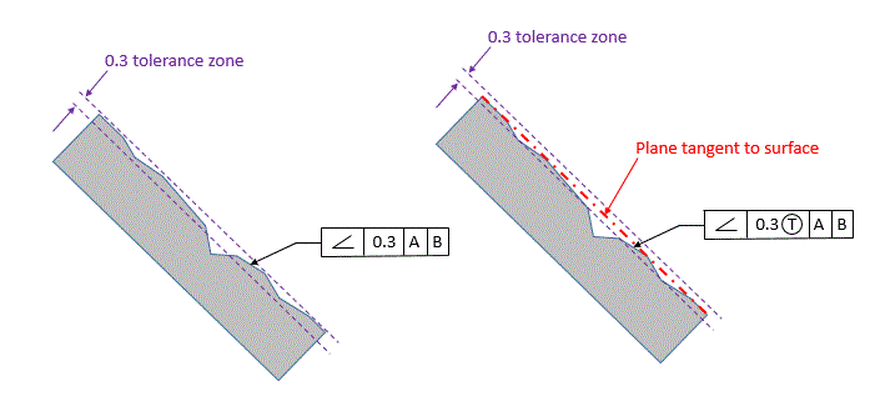
The tolerance zone lies on a plane that is perpendicular to the central axis of the circular feature Gauging / Measurement Circularity is measured by constraining a part, rotating it around the central axis while a height gauge records the variation of the surface The height gauge must have total variation less than the tolerance amountAngularity Datums Required Tolerance zone modifiers such as features of size;The tolerance indirectly controls the angle by controlling where the surface can lie based on the datum See the tolerance zone below for more details Maximum material condition or axis control can also be called out for angularity although the use in design and fabrication is very uncommon since gauging a hole or pin at an angle is difficult


Bend Tolerances Sheetmetal Me


An Angular Dimensional Tolerance Zone Download Scientific Diagram
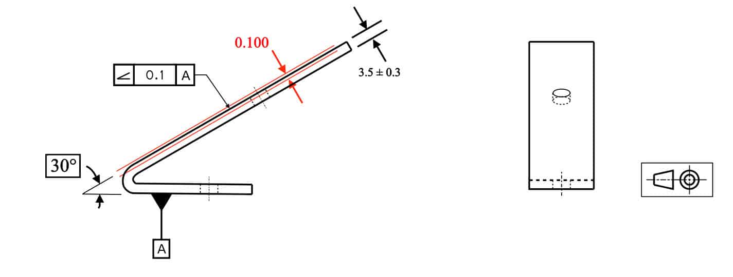
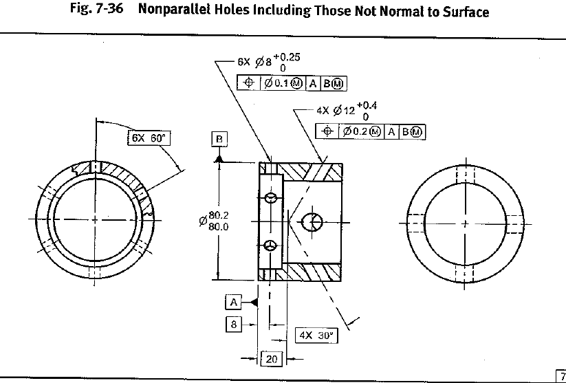
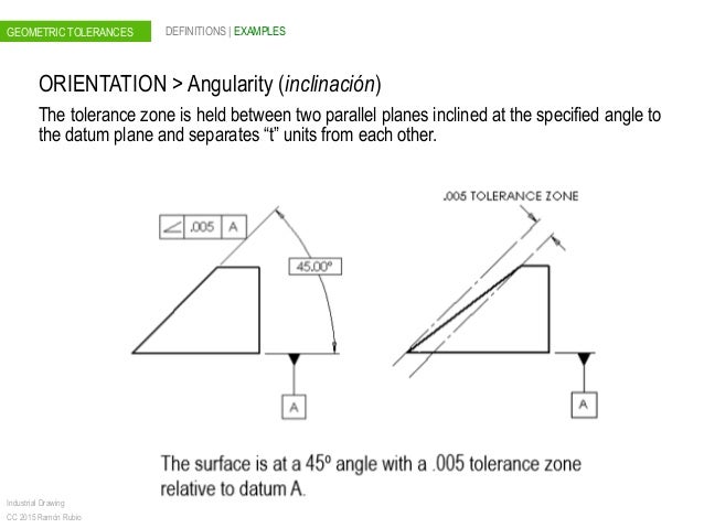
Angularity The tolerance zone is limited by two parallel planes a distance t apart and inclined at the specified angle to the datum Angularity tolerance of a line related to a datum surface ;The Tolerance of Position requirement mentioned above allows the dowel hole, and therefore the dowel, to tilt within its tolerance zone If there is a cover as shown below, a conflict can occur between the dowel and the cover The same situation applies to a threaded hole with a bolt that must clear a hole in the coverNow you would evaluate whether the hole axis falls within a zone constructed perpendicular to datum A (since no other angle is given


Form And Position Tolerances


Q Tbn And9gctok6pdlqkp8kfhuz5vz C6qihjckqmvrqyqf6vtclhvu6osctg Usqp Cau
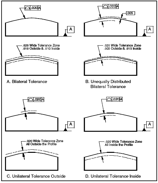
Angularity is the condition of a feature which is at any any angle other than parallel or perpendicular to a datum The tolerance zone will be a width between parallel planes or line A cylindrical tolerance zone is not applicable The dimension defining the angle between the datum and controlled feature must be basic and must be placed between the feature and datumA profile zone is presumed to be equally disposed around the perfect profile, but sometimes it is desired to have the zone be all to one side, or have a larger portion on one side than the other In former versions of Y145, it was accomplished by visually showing the tolerance zone on the drawing with one or more phantom linesSo Angularity symbol may be interchangeably used in place of Parallelism and Perpendicularity What is Parallelism in Drawing?


7 It Is Possible That Perpendicularity To Two Datums Could Have Been Specified Own On The Previo Homeworklib
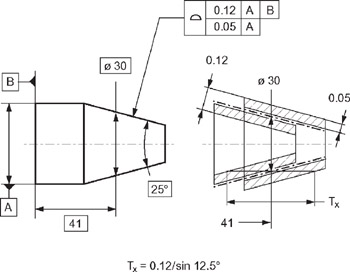


Chapter 5 Tolerancing Of Cones Engineering360
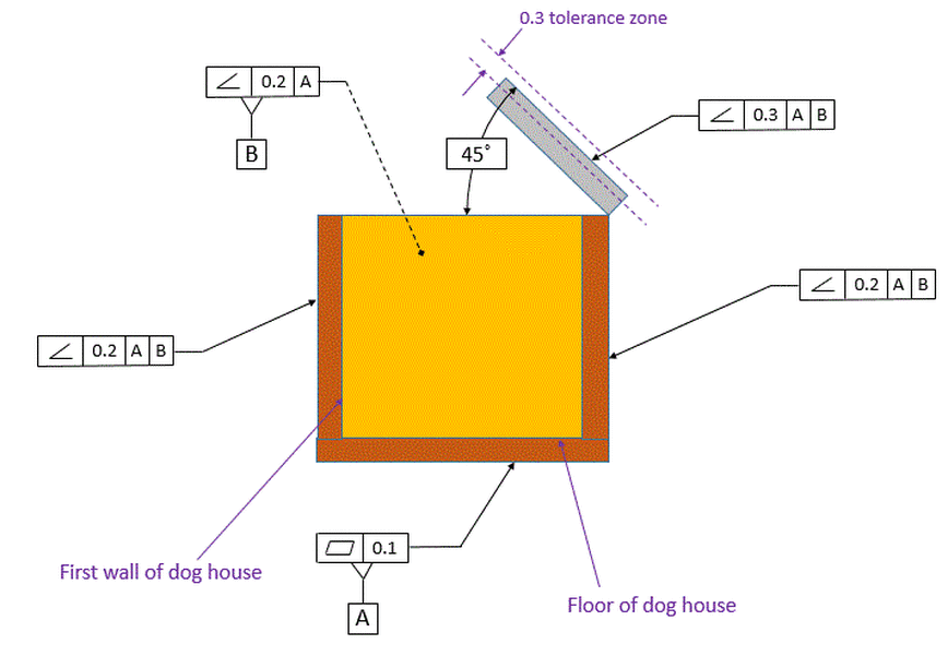
Angularity tolerance does not control the angle between two surfaces, planes, lines or features It creates a tolerance zone where all points of the controlled surface can lie When Angularity is applied over a surface, the tolerance zone will be two parallel surfaces, planes or lines to the true controlled surface All points on the controlled surfaces should lie within these limitsThe tolerance indirectly controls the angle by controlling where the surface can lie based on the datum See the tolerance zone below for more details Maximum material condition or axis control can also be called out for angularity although the use in design and fabrication is very uncommon since gauging a hole or pin at an angle is difficultAngularity applied on non feature of size creates tolerance zone consists of two parallel planes and all the surface elements must lies within tolerance zone When angularity is applied on cylindrical feature of size, tolerance zone is a cylinder, diameter of tolerance value referenced in feature control frame
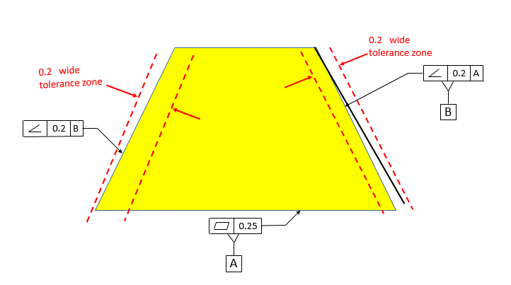


Angularity Dimensional Consulting
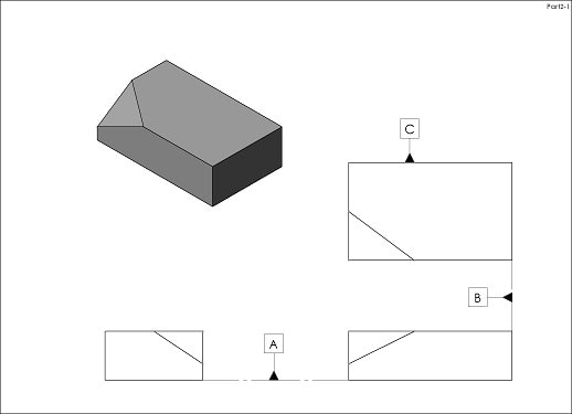


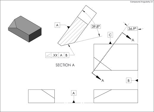
General Case Of Angularity Drafting Standards Gd T Tolerance Analysis Eng Tips
These circles would represent tolerance zones for circular runout taken at two locations on a plane perpendicular to the axis of rotation of AB The last zone in our discussion is known as 2 coaxial cylinders It's a common zone used in form, profile and runout controlsIn your example involving angularity to AB the tolerance zone would not change when you change the datum sequence only for an ideal part For an asproduced imperfect part the datums and the tolerance zone will not be coincident between the 2 scenarios AB versus BA Try to model an imperfect part and stabilize it according to each DRFConcentricity tolerance zone controls the median points of a feature of size Concentricity tolerance is a condition in which the axes of all crosssection elements of a feature's surface of revolution are common to the axis of a datum feature taper, angularity, and profile of a surface Total runout tolerance for a surface constructed


1


Gd T Tip Maximum Material Condition
So, finally, my options for angularity FCF are A or A, B, C The difference between the two is only the ability of the tolerance zone to rotate about B or not Of course, the location of the each tolerance zone is not fixed since they are angularity tolerancesAngularity Tolerance A tolerance zone defined by two parallel lines, two parallel planes, or a cylinder at a specified basic angle from one or more datum planes or datum axes within which the surface elements, surface, center plane, or axis of the considered feature must lieGD&T Profile Tolerancing PMPA Technical Conference Rapid Response to Make the Cut Corona, California Grand Rapids, MI April 11, 16 Gary K Griffith


Geometric Dimension And Tolerance Description With Drawing Projection


Gd T Angularity Definition Emachineshop
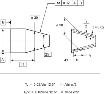
TOLERANCE ZONE DEFINITION (ASME Y145M1994) ACTUAL VALUE DEFINITION (ASME Y1451M1994) Angularity (line elements) For each line element, two parallel lines separated by the Orientation tolerance, which are oriented to the datum(s) Smallest Angularity tolerance to which the surface will conformConcentricity tolerance zone controls the median points of a feature of size Concentricity tolerance is a condition in which the axes of all crosssection elements of a feature's surface of revolution are common to the axis of a datum feature taper, angularity, and profile of a surface Total runout tolerance for a surface constructedThe tolerance zone of a geometric tolerance constraint is the maximum allowed deviation in all directions for a dimensioned feature on a part For example, the tolerance zone of a feature constrained with a roundness tolerance will be in the shape of the space between 2 concentric circles because the edges of the allowed deviation take the same


Geometric Dimensioning Tolerancing Gd T Symbols Basics


Geometric Dimensioning And Tolerancing Gd T Management Customers Vendors
No Angularity is an orientation control and uses a tolerance zone similar to parallelism and perpendicularity The angle is BASIC I've actually seen an argument for using one symbol for all 3 and just specify the angle relation ship between the feature and the datumThe Tolerance of Position requirement mentioned above allows the dowel hole, and therefore the dowel, to tilt within its tolerance zone If there is a cover as shown below, a conflict can occur between the dowel and the cover The same situation applies to a threaded hole with a bolt that must clear a hole in the coverA profile zone is presumed to be equally disposed around the perfect profile, but sometimes it is desired to have the zone be all to one side, or have a larger portion on one side than the other In former versions of Y145, it was accomplished by visually showing the tolerance zone on the drawing with one or more phantom lines


How Gd T Form Tolerances Affect Shaft Fits Misumi Blog


Angularity Gd T Basics


Gd T Geometric Dimensioning And Tolerancing Orientation Tolerances Perpendicularity Angularity Parallelism


Orientation Tolerance Types Of Geometric Tolerances Gd T Fundamentals Keyence America


Q Tbn And9gctjjmvdp7cnum9uoms9xj1rom7rxqz7qntxfxr C30i5vcxyyhc Usqp Cau


Gd T Guide By Padmabhushan V Sali Posts Facebook


Angularity Gd T Basics


Geometric Dimensioning Tolerancing Ppt Video Online Download


Perpendicularity Gdt Youtube


Q Tbn And9gcqbvwryag06vk9wgcwdxd Qvw8ef2n9frgzlx7ldjvjqktymwct Usqp Cau


Week 9 2d Detailing Challenge Skill Lync


Measuring Angularity Measuring With Datums Orientation Tolerance Gd T Fundamentals Keyence America


Pdf Tolerance Stack Up Analysis For Angularity Of Components And Their Assembly Semantic Scholar


Tdc Of Az Gd T Training Tolerance Stack Up Training


Angularity Dimensional Consulting


Perpendicularity Of An Axis


05 Orientation Tolerances Cartesian Coordinate System Plane Geometry


Gd T Blog Geometric Learning Systems


Geometric Dimensioning And Tolerancing Wikipedia


Visual Refresher On Geometric Dimensioning Tolerancing


Angularity Gd T Basics


Www Abdiecasting Com Wp Content Uploads 17 09 Section 05 Geometric Dimensioning Pdf


Etshare Pbworks Com F Orientation controls Pdf


0199b Angularity Parallelism Or Perpendicularity With Implied Flatness


Geometric Dimensioning And Tolerancing Principles And Practices 10e Page 281 299 Of 592


Gd T Functionality 13 01 03 Quality Magazine


Angularity Dimensional Consulting


Gd T Perpendicularity Definition Emachineshop


Http Eon Sdsu Edu Johnston Me102 Lecture Notes Gtol lecture 4 orientation Orientation applied to features Pdf


Solved Als We 1 A Real World Application Of A Parallelism Chegg Com


Chapter 5 Tolerancing Of Cones Engineering360
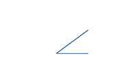


Easy Guide To Gd T Angularity Symbol Tolerance Measurement


Solved F 1 When An Angularity Tolerance Is Applied To A Chegg Com


Cstools Asme Org Csconnect Filedownload Cfm Thisfile Publicreviewdraft2370 Pdf Dir Ansi Bsr8 431 515


Geometrical Tolerance An Overview Sciencedirect Topics


Gd T Symbol Relative To Datum Yes Mmc Or Lmc Applicable Yes Uncommon Drawing Callout Space Geometry


What Is Perpendicularity Tolerance And How To Interpret In The Drawing Mechstandard


16 Gd T Angularity Flashcards Quizlet


Geometric Boundaries Iv The Interpretation And Application Of Gd T Engineering Books And Supplies Store
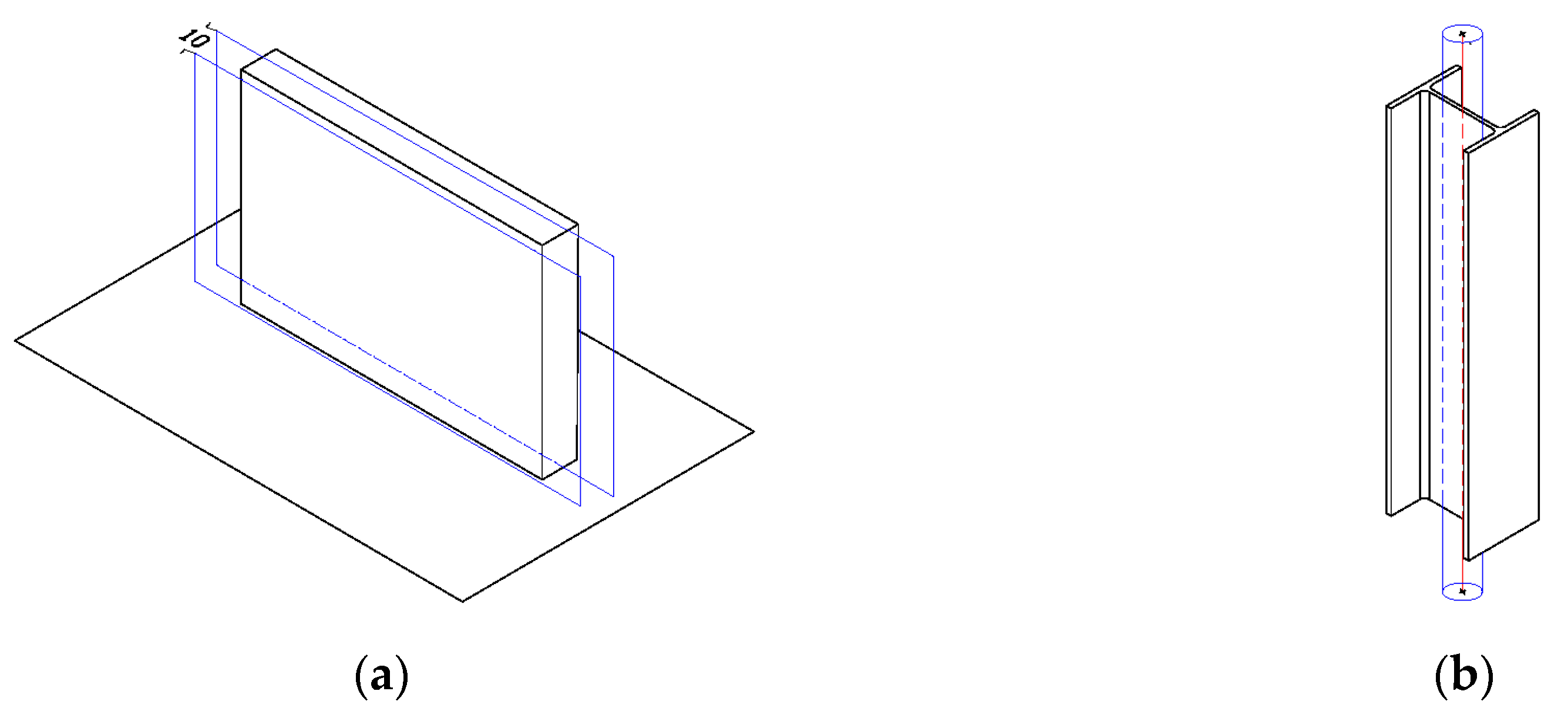


Buildings Free Full Text Deploying Geometric Dimensioning And Tolerancing In Construction Html


Http Files Engineering Com Download Aspx Folder B437 45 9df0 af2de File What Is Gdtbasic Pdf


What Is Angularity Tolerance And How To Interpret In The Drawing Mechstandard


Http Eon Sdsu Edu Johnston Me102 Lecture Notes Gtol lecture 4 orientation Orientation applied to features Pdf


An Angular Dimensional Tolerance Zone Download Scientific Diagram


Geometric Dimensioning And Tolerancing Manufacturinget Org


Angularity Tolerance In Gd T Geometric Dimension And Control


What Is The Effect Of Specifying This Angularity Tolerance On A Surface The Course Hero
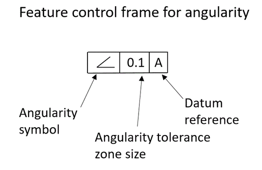


Angularity Dimensional Consulting
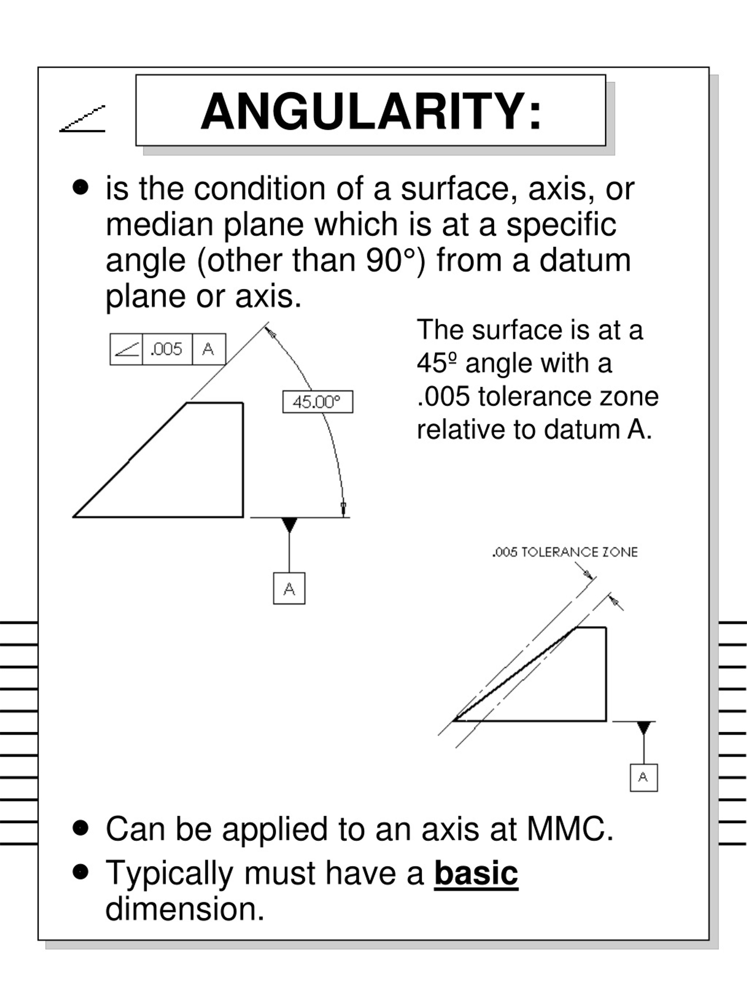


Ppt Geometric Dimensioning Tolerancing Ansi Y14 5m 1994 Powerpoint Presentation Id


Www Abdiecasting Com Wp Content Uploads 17 09 Section 05 Geometric Dimensioning Pdf


Easy Guide To Gd T Angularity Symbol Tolerance Measurement


16 Gd T Angularity Flashcards Quizlet


Etshare Pbworks Com F Orientation controls Pdf
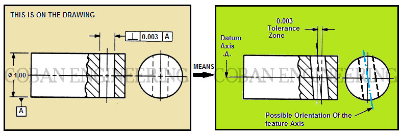


Gd T Geometric Dimensioning And Tolerancing Orientation Tolerances Perpendicularity Angularity Parallelism
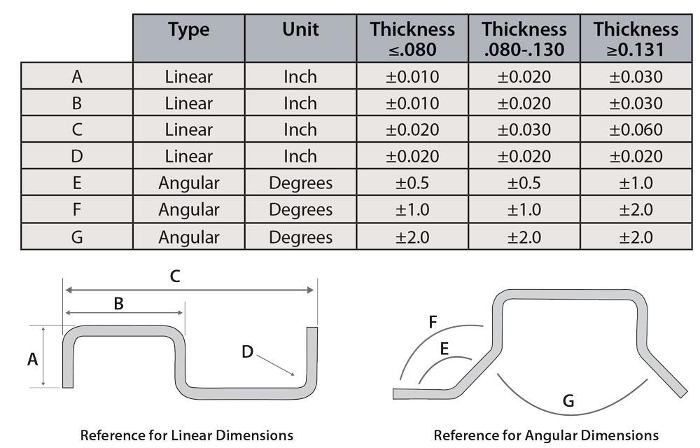


Reasonable Tolerancing For Press Brake Bending


How Gd T Form Tolerances Affect Shaft Fits Misumi Blog
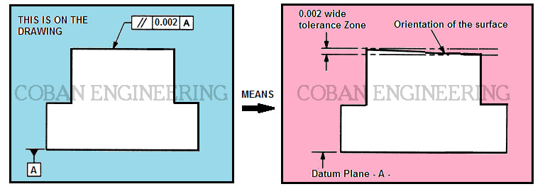


Gd T Geometric Dimensioning And Tolerancing Orientation Tolerances Perpendicularity Angularity Parallelism


General Case Of Angularity Drafting Standards Gd T Tolerance Analysis Eng Tips


Hole Position Tolerance Ptc Community


18 Solidworks Help Linear And Angular Tolerances


05 Geometric Tolerances


Based On The Asme Y14 5m Dimensioning And Tolerancing Standard Dimensional Engineering Ppt Download


The Basics Of Geometric Dimensioning And Tolerancing Gd T Formlabs


Gd T Tips Feature Control Frame


Wall Thickness Tolerance Stack Tes Rnd


Measuring Angularity Measuring With Datums Orientation Tolerance Gd T Fundamentals Keyence America


Perpendicularity Of A Surface
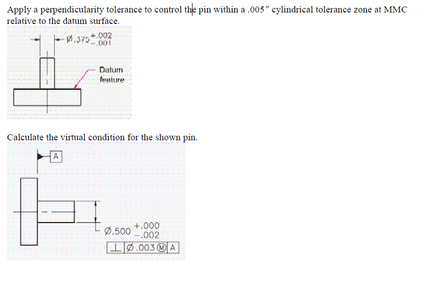


Answered Apply A Perpendicularity Tolerance To Bartleby


Perpendicularity Of A Surface


Gd T Tolerance Zone Control Symbols


Easy Gd T Perpendicularity Symbol Tolerance Measurement


Projected Tolerance Zone Equivalent To Tightening The Zone Geometric Learning Systems


Gd T Geometric Dimensioning And Tolerancing Orientation Tolerances Perpendicularity Angularity Parallelism


Gd T Guide


Perpendicularity Tolerance In Gd T Smlease Design


Http Users Encs Concordia Ca Home C Cheung Document save Mech313 Design Lectures Lectures L 7 8 Ch16 L7 8 Ch16 Lecture 8 Gt V2 Pdf


Solved Workshop Exercise 11 1 Front View Side View All An Chegg Com


Gd T Quiz


コメント
コメントを投稿